Page 245 - Каталог
P. 245

ПОСМОТРЕТЬ ВСЕ ТЕХНИЧЕСКИЕ
                ЧЕРТЕЖИ FXDQ-A3 НА MY.DAIKIN.EU
                                                                                 Подробные технические чертежи       VRV,   ВСТУПЛЕНИЕ
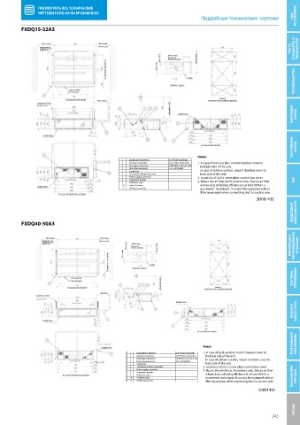
          FXDQ15-32A3
          FXDQ15-32A

                  300 or more           300 or more
                 (Service space of      (Service space)                                                               СТАНДАРТЫ И
                 installation box for                                                                                VRV IV,   ТЕХНОЛОГИИ
                 adapter PCB)
                                                                20 or more  400 or more  240 or more
                                                                    (In case of
                                                                    bottom-suction)
                                           (Suspension bolt pitch)  20 or more

                                                                     Service space  Ceiling                           ПРЕИМУЩЕСТВА
                            16x ø 4,7 holes
                                                                                        View A
                           (Suspension bolt pitch)  300 or more                     Inspection door (ceiling opening)
                                                                    Adjustable (0-600)  16xM5 holes                  НАРУЖНЫЕ   БЛОКИ
                Suspension bolt


                  14xM4 holes
                                                                                                                     ВНУТРЕННИЕ   БЛОКИ
                                                                                 In case of back suction
                                                                               Notes:
                                                  1   Liquid pipe connection   ø 6.4 Flare connection
                                                  2   Gas pipe connection   ø 12.7 Flare connection  1. In case of back-suction, mount chamber cover to
                                                  3   Drain pipe connection   VP20 (O.D. ø  26, I.D. ø  20)      botttom side of the unit.
                                                  4   Drain hose (accesory)   ID  ø  25 (Outlet)      In case of bottom-suction, mount chamber cover to
                                                  5   control box
                                                  6   Transmisiion wiring connection      back side of the unit.
                                                  7   Power supply connection  2. Locations of unit`s name plate: control box cover.
                                                  8    Suspension bracket      3. Mount the air  lter at the suction side. (Use an air  lter  ГВС
                                                  9   Inspection cover
                                                  10   Socket for drain            whose dust collecting e ciency is at least 50% in a
                16xM5 holes
                                                  11   Air  lter (accessory)       gravimetric technique). It can not be equipped with air
                                                                                    lter (accessory) when connecting duct to suction side.
                        In case of bottom-suction
                                                                                                       3D081435
                                                                                                                     ВОЗДУШНАЯ   ЗАВЕСА BIDDLE
          FXDQ40-50A3
          FXDQ40-50A

                   300 or more           300 or more
                  (Service space of      (Service space)
                  installation box for
                                                   20 or more 20 or more  (In case of   240 or more                    УСТАНОВКИ
                  adapter PCB)                       400 or more                                                    ВЕНТИЛЯЦИЯ И   ВЕНТИЛЯЦИОННЫЕ
                                                     bottom-suction)
                                            (Suspension bolt pitch)  Service space  Ceiling


                                                                 Adjustable (0-600)
                              22 x ø 4,7 hole                                                                        СИСТЕМЫ   УПРАВЛЕНИЯ
                                                                                      View A
                            (Suspension bolt pitch)                               Inspection door (ceiling opening)
                                         300 or less
               Suspension bolt
                                                                       20xM5 holes
                                                                                                                     ОПЦИИ И   АКСЕССУАРЫ

                  18xM4 holes

                                                                               In case of back suction
                                                                                                                     ПРОГРАММЫ И   ПЛАТФОРМЫ
                                                                                  Notes:
                                         20xM5 holes
                                                     1   Liquid pipe connection   ø 6.4 Flare connection  1. In case of back-suction, mount chamber cover to
                                                     2   Gas pipe connection   ø 12.7 Flare connection      botttom side of the unit.
                                                     3   Drain pipe connection   VP20 (O.D. ø  26, I.D. ø  20)      In case of bottom-suction, mount chamber cover to
                                                     4   Drain hose (accesory)   ID  ø  25 (Outlet)
                                                     5   control box                  back side of the unit.
                                                     6    Transmission wiring connection  2. Locations of unit`s name plate: control box cover.
                                                     7    Power supply connection  3. Mount the air  lter at the suction side. (Use an air  lter
                                                     8   Suspension bracket
                          In case of bottom-suction  9   Inspection cover                                        whose dust collecting e ciency is at least 50% in a   ТЕХНИЧЕСКИЕ   ЧЕРТЕЖИ
                                                     10   Socket for drain            gravimetric technique). It can not be equipped with air
                                                     11   Air  lter (accessory)        lter (accessory) when connecting duct to suction side.
                                                                                                       3D081436
                                                                                                                      НАЗАД Технические чертежи
                                                                                                             243
   240   241   242   243   244   245   246   247   248   249   250