
Page 242 - Каталог
P. 242
ПОСМОТРЕТЬ ВСЕ ТЕХНИЧЕСКИЕ
ЧЕРТЕЖИ FXCQ-A НА MY.DAIKIN.EU
Подробные технические чертежи
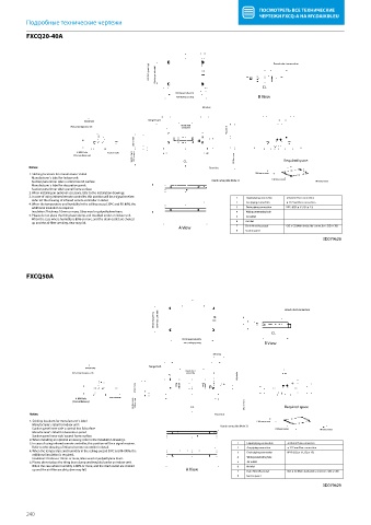
FXCQ20-40A
FXCQ20-40A
640 (Ceiling opening) 520 (Hanger bolt pitch) Branch duct connection
CL
820 (Hanger bolt pitch)
B View
1030 (Ceiling opening)
300 or less
Hanger bolt
(Knock hole)
Branch duct
Pitch center diameter ø 176
Adjustable
connection
355 or more
4-M4 Hole Fresh air intake
Suction space 1000 or more CL 2500 or more Required space
(Circumference)
Notes: Floor line
1. Sticking locations for manufacturer`s label 1500 mm or more
Manufacturer`s label for indoor unit:
Suction panel inner side`s control box lid surface Brand name plate (Note 3) 1500 mm or more 100 mm or more
Manufacturer`s label for decoration panel:
Suction panel inner side`s panel frame surface
2. When installing an optional accessory, refer to the installation drawings.
3. In case of using infrared remote controller, this position will be a signal receiver. 1 Liquid piping connection ø 6.4 mm Flare connection
Refer tot the drawing of infrared remote controller in detail.
4. When the temperature and humidity in the ceiling exceed 30ºC and RH 80%, the 2 Gas piping connection ø 12.7 mm Flare connection
additional insulation is required. 3 Drain piping connection VP25 (O.D. ø 32, I.D. ø 25)
Insulation: Thickness 10mm or more, Glass wool or polyethylene foam. 4 Wiring penetrating hole
5. Please do not place the thing been damp and troubled under an indoor unit. 5 Air outlet
When the case where humidity is 80% or more, and the drain outlet are choked
up and the air lter are dirty, dew may fall. 6 Air inlet
A View 7 Drain Hose (Accesory) O.D. ø 32 (Main body side connection : O.D. ø 26)
8 Suction panel
3D079628
FXCQ50A
FXCQ50A
Branch duct connection
640 (Ceiling opening) 520 (Hanger bolt pitch)
CL
1035 (Hanger bolt pitch)
1245 (Ceiling opening) B View
300 or less
Hanger bolt
(Knock hole)
Branch duct
Pitch center diameter ø 176 connection
Adjustable
355 or more
4-M4 Hole Fresh air intake
Suction space 1000 or more CL 2500 or more Required space
(Circumference)
Notes: Floor line
1. Sticking locations for manufacturer`s label 1500 mm or more
Manufacturer`s label for indoor unit: Brand name plate (Note 3)
Suction panel inner side`s control box lid surface 1500 mm or more 100 mm or more
Manufacturer`s label for decoration panel:
Suction panel inner side`s panel frame surface
2. When installing an optional accessory, refer to the installation drawings.
3. In case of using infrared remote controller, this position will be a signal receiver. 1 Liquid piping connection ø 6.4mm Flare connection
Refer tot the drawing of infrared remote controller in detail. 2 Gas piping connection ø 12.7 mm Flare connection
4. When the temperature and humidity in the ceiling exceed 30ºC and RH 80%, the 3 Drain piping connection VP25 (O.D. ø 32, I.D. ø 25)
additional insulation is required.
Insulation: Thickness 10mm or more, Glass wool or polyethylene foam. 4 Wiring penetrating hole
5. Please do not place the thing been damp and troubled under an indoor unit. 5 Air outlet
When the case where humidity is 80% or more, and the drain outlet are choked 6 Air inlet
up and the air lter are dirty, dew may fall. A View 7 Drain Hose (Accesory) O.D. ø 32 (Main body side connection : O.D. ø 26)
8 Suction panel
3D079629
240