Page 240 - Каталог
P. 240

ПОСМОТРЕТЬ ВСЕ ТЕХНИЧЕСКИЕ
                                                                                    ЧЕРТЕЖИ FXFQ-B НА MY.DAIKIN.EU
          Подробные технические чертежи
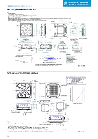
          FXFQ-B С ДИЗАЙНЕРСКОЙ ПАНЕЛЬЮ
         FXFQ-B
          Notes
           1. Location of nameplate
           The unit nameplate is located on the control box cover.
           The decoration panel nameplate is located on the piping-side panel frame, under the corner cover.
           2. When installing optional accessories, refer to thei r respective documentation.
           3. Make sure the distance between the ceiling and the cassette does not exceed ·35·mm.
           The maximum ceiling opening is ·910·mm.
           4. When the conditions in the ceiling exceed 30°C ambient temperature and 80% relative humidity, or when fresh air is inducted into the ceiling, additional insulation is required (polyethylene foam, thickness ≥·10·mm).
           5. When installing a sensor kit, there will be a sensor on this location. For details, see the drawing of the sensor kit.
           6. When installing a wireless controller, there will be a receiver on this location. For details, see the drawing of the wireless controller.
                      ·300·  or less                           See         7  6  8
                                                                           note ·5·.
                             420                                                     Drain side

                                                                                           DETAIL  A  DETAIL A
                                                                                                   ·2· places
                                                                                         ·2· places  Opposite side
                                                                                        Opposite side
                                            Suspension position                                80       80
                                                                                                     53
                      9                       See note ·3·.  A                             54.5 54.5 96.5  67 96.5
                                           780  860-910  213   950                       25.4  100  25.4  100
                                              Ceiling opening  Ø75                     350  121.5  100  350  121.5  100
                                                 10
                                                                                            95  80      80
                             420                      AB
                                                                                   Piping side   FCAG35/50/60/71BVEB
                                710                          See note ·6·.  950       FCAG100/125/140BVEB  FXFQ20/25/32/40/50/63BVEB
                             Suspension position                                      FCAHG71/100/125/140HVEB
                               860-910                                                FXFQ80/100/125BVEB
                          Ceiling opening  See note ·3·.  840             DETAIL  B
                                                                                           DETAIL B
                         55     840     55           340   4  1  2        ·2· places       ·2· places
                             B                 0-675  Adjustable  3      Opposite side    Opposite side
                                            172                             350              350
                   C                           217  52            152  192  AA  121.5        121.5
                                             ·2700·  or more  330
                        35               35   Required installation space  45  280  54.5  54.5  95  81  100  100  85  53  67
                                     5        4 - M8        M10        96.5  81  100  100  85       96.5
                                                 OR
                       See note ·3·.  See note ·3·.  Suspension bolt      FCAG100/125/140BVEB  FCAG35/50/60/71BVEB
                                                     ARROW VIEW C
                                                                          FCAHG71/100/125/140HVEB
                                                                          FXFQ80/100/125BVEB  FXFQ20/25/32/40/50/63BVEB
                                                                                 Item Name
                     Respect the distances shown on the  gure.  ·1500·  or more  1  Liquid pipe connection port
                    Ceiling-mounted lighting  Air fan  Other unit  ·200·  or more  2  Gas pipe connection port
                                                                                 3  Drain pipe connection
                                                 ·1500·  or more      ·1500·  or more  4  Power supply wiring intake
                                                                                  5  Transmission wiring intake hole
                   ·1500·  or more                    ·200·  or more  ·1500·  or more  6  Air discharge outlet
                          ·2000·  or more                                         7  Flat grille assembly
                                                                                   Corner decoration cover
                             ·4000·  or more          Required installation space  8 9  Drain hose
                                            If a discharge outlet is closed up with the "sealing member" option kit, then the required  10 Knockout hole.
                                                                                                2D121703
                                            installation space on that (closed up) side is ·500·mm instead of ·1500·mm.
          FXFQ-B С ЗАБОРОМ СВЕЖЕГО ВОЗДУХА
          FXFQ-B                                                                  AA  AB   Model name
                                                                                  264  306  FCAG35/50/60/71BVEB
                                                                                        FXFQ20/25/32/40/50/63BVEB
                  55         840        55  Duct                                  306  348  FCAG100/125/140BVEB
                                          Left side                                     FXFQ80/100BVEB
                                                 Piping side                      348  390  FCAHG71/100/125/140HVEB
                                                                                        FXFQ125BVEB
                                                                           See note ·3·.
                                          328  427                                     140
                                                                                       130
                 840                                                                   120
                                                                                       110
                                                                                       100
                                          328  427                                      90
                                                                                        80
                                                 Drain side                See note ·3·.  Static pressure in chamber [Pa]  70
                                                                                        60
                                                                                        50
                                                                                        40
                                 448      Duct   Service access panel  View ·A·  (1000)  30
                                                                                        20
                                  508     Right side  ·450 x 450 mm·  or more           10
                                         Ø148    See note ·1·.                          0  Air  ow rate [m³/min] 5 3  6
                                                                                                 1
                                                                                                  4
                                                                                             2
                 AA                          275
                                           165
               Suction chamber   455                                    T-joint
              Decoration panel  Ceiling opening           725        Field supply
                               A                                       Inlet     Ø148
                                                        AB                          317
                                                                                   207
         Notes
                                                      Suction chamber
         1. When installing a fresh air intake kit, provide a service access panel.  Designer decoration panel  455
         2. Field construction                                       Ceiling opening
         3. This corner discharge outlet needs to be closed.
         4. When installing a duct fan, use a wiring adapter to link the duct fan to the fan of the indoor unit.
         5. The intake air  ow rate is recommended to be ≤20% of the air  ow rate at high fan speed.
         If the intake air  ow rate is too large, the operating sound may increase, and the detection of the indoor unit suction temperature may be a ected.
         6. This indicates the distance between the T-joint inlet and the indoor unit inlet when the T-tube is connected.   3D121741
          238
   235   236   237   238   239   240   241   242   243   244   245