Page 244 - Каталог
P. 244

ПОСМОТРЕТЬ ВСЕ ТЕХНИЧЕСКИЕ
                                                                                    ЧЕРТЕЖИ  FXKQ-MA НА MY.DAIKIN.EU
          Подробные технические чертежи
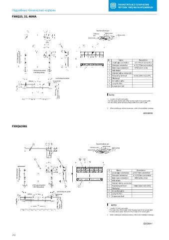
          FXKQ25, 32, 40MA
          FXKQ25,32,40MA


                                                                     Required installation space
                                                                   1,500 mm or   200 mm or more
                                                                   more             200 mm or more
                                                               20 mm or more


              760 (Ceiling opening)  350 (Suspension position)               Nr.     Name          Description


                                                                                                ø 6.4 Flare connection
                                                                              2 1  Liquid pipe connection  ø 12.7 Flare connection
                                                                                Gas pipe connection
                                                                              3  Drain pipe connection  VP25 (O.D. ø 32)
                        1,150 (Suspension position)                           4  Wire intake
                         1,200 (Ceiling opening)                              5  Interunit wiring connection
                                                                              6  Grounding terminal  Inside switch box (M4)
                                        Front discharge duct position         7  Discharge
                     4-M4 hole        Suspension bolt                         8  Air suction grille
                                                                              9  Long life filter
                                                                              10  Suspension bolt
                                         1,000 or more  Required installation  NOTES

                                            space
                                                                             1
                                                                               Location of unit’s name plate:
                                                                             • For main body: Bottom part of fan housing inside of air suction grille.
                                                                             • For decoration panel: Service lid face inside of air suction grille.
                                                                             2  When installing an optional accessory, refer to the installation drawings.
                                                                                                      3D038840


          FXKQ63MA
          FXKQ63MA


                                                                     Required installation space
                                                                         200 mm or more
                                                                1,500 mm or more  200 mm or more
                                                               20 mm or more


             760 (Ceiling opening)  350 (Suspension position)                 1 2 . r N  Liquid pipe connection         ø 9.5 Flare connection
                                                                                   Name
                                                                                                 Description
                                                                                Gas pipe connection            ø 15.9 Flare connection
                                                                                Wire intake
                                                                              4 3  Drain pipe connection  VP25 (O.D. ø 32)
                                                                              5  Interunit wiring connection
                        1,350 (Suspension position)                           6  Grounding terminal  Inside switch box (M4)
                        1,400 (Ceiling opening)
                                                                              7  Discharge
                                         Front discharge duct position        8  Air suction grille
                    6-M4 hole           Suspension bolt                       9  Long life filter
                                                                              10  Suspension bolt
                                          1,000 or more  (Required   installation space)  NOTES

                                                                               Location of unit’s name plate:
                                                                               1  • For main body: Bottom part of fan housing inside of air suction grille.
                                                                                • For decoration panel: Service lid face inside of air suction grille.
                                                                            2  When installing an optional accessory, refer to the installation drawings.

                                                                                                      3D038841


          242
   239   240   241   242   243   244   245   246   247   248   249