Page 239 - Каталог
P. 239

ПОСМОТРЕТЬ ВСЕ ТЕХНИЧЕСКИЕ
                ЧЕРТЕЖИ FXFQ-B НА MY.DAIKIN.EU
                                                                                 Подробные технические чертежи       VRV,   ВСТУПЛЕНИЕ
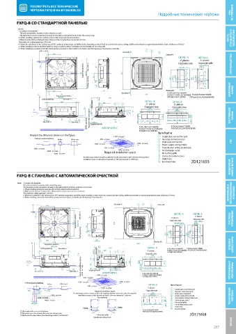
          FXFQ-B СО СТАНДАРТНОЙ ПАНЕЛЬЮ
         FXFQ-B
          Notes
          1. Location of nameplate
             The unit nameplate is located on the control box cover.
             The decoration panel nameplate is located on the piping-side panel frame, under the corner cover.
          2. When installing optional accessories, refer to their respective documentation.                          VRV IV,   СТАНДАРТЫ И   ТЕХНОЛОГИИ
          3. Make sure the distance between the ceiling and the cassette does not exceed ·35·mm.
          The maximum ceiling opening is ·910·mm.
          4. When the conditions in the ceiling exceed 30°C ambient temperature and 80% relative humidity, or when fresh air is inducted into the ceiling, additional insulation is required (polyethylene foam, thickness ≥·10·mm)
          5. When installing a sensor kit, there will be a sensor on this location. For details, see the drawing of  the sensor kit.
          6. When installing a wireless controller, there will be a receiver on this location. For details, see the drawing of the wireless controller.
                     ·300·  or less                            See         7  6  8
                                                                           note ·5·.
                            420                                                      Drain side

                                                                                           DETAIL  A  DETAIL A
                                                                                                      ·2· places
                                                                                            ·2· places  Opposite side
                                           Suspension position                                 80
                     9                        See note ·3·.  A                             Opposite side  67 53  96.5  ПРЕИМУЩЕСТВА
                                                                                            54.5
                                                                                             54.5 96.5
                                          780  860-910  213    950                       25.4  100  25.4  80  100
                                              Ceiling opening  Ø75                     350  121.5  100  80  350  121.5  100  80
                                                 10

                            420                      AB                              Piping side  95                 НАРУЖНЫЕ   БЛОКИ
                                                                  See note ·6·.      FCAG100/125/140BVEB
                               710                                        950        FCAHG71/100/125/140HVEB  FCAG35/50/60/71BVEB
                             Suspension position                                     FXFQ80/100/125BVEB
                               860-910                  840                                      FXFQ20/25/32/40/50/63BVEB
                      Ceiling opening  See note ·3·.
                        55      840    55            340   4  1  2        DETAIL  B     DETAIL B
                                                                           ·2· places
                                                                                         ·2· places
                                               0-675  Adjustable  3       Opposite side  Opposite side
                                                                            350
                                                                                          350
                  C                         130  175 2D121655     110  150  AA  121.5    121.5
                                                10
                                             ·2700·  or more  Suspension bolt  FCAG100/125/140BVEB  FCAG35/50/60/71BVEB
                       35       B        35   Required installation space  40  280  54.5  54.5  95  81  100  100  85  53  67  ВНУТРЕННИЕ   БЛОКИ
                       See note ·3·.  5 See note ·3·.  4 - M8        M10  330  96.5  81  100  100  85  96.5
                                                OR
                                                    ARROW VIEW C
                                                                       FCAHG71/100/125/140HVEB
                                                                       FXFQ80/100/125BVEB  FXFQ20/25/32/40/50/63BVEB
                                                                                 Item Name
                Respect the distances shown on the  gure.
                                                          ·1500·  or more        1  Liquid pipe connection port
                   Ceiling-mounted lighting  Air fan  Other unit  ·200·  or more  2  Gas pipe connection port
                                                                                 3  Drain pipe connection             ГВС
                                                ·1500·  or more       ·1500·  or more  4  Power supply wiring intake
                  ·1500·  or more                    ·200·  or more  ·1500·  or more  5  Transmission wiring intake hole
                         ·2000·  or more              Required installation space  6  Air discharge outlet
                            ·4000·  or more                                      7  Air suction grille
                                           If a discharge outlet is closed up with the "sealin g member" option kit, then the required  8  Corner decoration cover
                                           installation space on that (closed up) side is ·500·mm instead of ·1500·mm.  9  Drain hose
                                                                                                                     ВОЗДУШНАЯ   ЗАВЕСА BIDDLE
                                                                                 10 Knockout hole.  2D121655
          FXFQ-B С ПАНЕЛЬЮ С АВТОМАТИЧЕСКОЙ ОЧИСТКОЙ
          FXFQ-B
         FXFQ-B
          Notes
             1. Location of nameplate
             The unit nameplate is located on the control box cover.
         Notes  1. Location of nameplate
             The decoration panel nameplate is located on the piping-side panel frame, under the corner cover.
             2. When installing optional accessories, refer to their respective documentation.
            The unit nameplate is located on the control box cover.
             3. Make sure the distance between the ceiling and the cassette does not exceed ·35·mm.
            The decoration panel nameplate is located on the piping-side panel frame, under the corner cover.
             The maximum ceiling opening is ·910·mm.
            2. When installing optional accessories, refer to their respective documentation.                       ВЕНТИЛЯЦИЯ И   ВЕНТИЛЯЦИОННЫЕ   УСТАНОВКИ
             4. When the conditions in the ceiling exceed 30°C ambient temperature and 80% relative humidity, or when fresh air is inducted into the ceiling, additional insulation is required (polyethylene foam, thickness ≥·10·mm).
            3. Make sure the distance between the ceiling and the cassette does not exceed ·35·mm.
            The maximum ceiling opening is ·910·mm.
             5. When installing a sensor kit, there will be a sensor on this location. For details, see the drawing of the sensor kit.
            4. When the conditions in the ceiling exceed 30°C ambient temperature and 80% relative humidity, or when fresh air is inducted into the ceiling, additional insulation is required (polyethylene foam, thickness ≥·10·mm).
                                                                         6
                                                           See note ·5·.
                 ·300·  or less

            5. When installing a sensor kit, there will be a sensor on this location. For details, see the drawing of the sensor kit.       7  8  Drain side
                         420
                 ·300·  or less                            See note ·5·.  7  6   Drain side

                        420                                                  8
                                                                                                   DETAIL A
                                                                                         DETAIL  A
                                                                                                    ·2· places
                   9                      See note ·3·.  A                              ·2· places  DETAIL A
                                                                                         DETAIL  A
                                                                                                   ·2· places
                                                                                                    67 96.5
                   9                    Suspension position  See note ·3·.  A          Opposite side  Opposite side
                                                                                       ·2· places
                                                                                                    53
                                                                                         54.5
                                                                                           54.5 96.5
                                       780  Suspension position  860-910  950          Opposite side  Opposite side  СИСТЕМЫ   УПРАВЛЕНИЯ
                                                                                                    67 96.5
                                      780  860-910  213  Ø75 213  950                  25.4  54.5 54.5 96.5 80  100  25.4  53  80  80  100
                                                                                             80
                                          Ceiling opening  Ceiling opening  Ø75  10  350  121.5  25.4  100  100  350  121.5  25.4  100  100
                         420                  10  AB                                     350  121.5  350  121.5
                            710                                                Piping side   100  80  100  80
                        Suspension position      AB                    950                95  80
                        420
                            710
                           860-910                                             Piping side            80
                       Suspension position
                      Ceiling opening  See note ·3·.    840           950   DETAIL  B  FCAG100/125/140BVEB  FCAG35/50/60/71BVEB  ОПЦИИ И   АКСЕССУАРЫ
                                                                                          95
                            840
                     55    860-910  55            Adjustable  340  4  1  2  ·2· places  FCAHG71/100/125/140HVEB  FXFQ20/25/32/40/50/63BVEB
                                                                            DETAIL  B
                                                                                      FXFQ80/100/125BVEB
                      Ceiling opening  See note ·3·.  0-675  3  840        Opposite side  FCAG100/125/140BVEB  FCAG35/50/60/71BVEB
                                                                              350
                     55     840    55    210      Adjustable  3  340  4  1  2  ·2· places  FCAHG71/100/125/140HVEB  FXFQ20/25/32/40/50/63BVEB
                                                                                     FXFQ80/100/125BVEB
                                                                             121.5
                                         210    AA  255 0-675              Opposite side
                                                                             350
                                                                             121.5
               C           B              Required installation space  AA  90  255  190  230  230  54.5  54.5  54.5  95
               C   35      B     5    35       90  40  4 - M8          M10  280  190  54.5  96.5  81  100  100  85  95
                                                   OR
                                                           330
                   See note ·3·.     See note ·3·. Required installation space  ·2700·  or more  Suspension bolt  81  100  100  85
                                                          280
                  35            5     35       40  4 - M8          M10 ARROW VIEW C  96.5  FCAG100/125/140BVEB       ПРОГРАММЫ И   ПЛАТФОРМЫ
                                                   OR
                                                           330
                                              Suspension bolt
                                                                         FCAHG71/100/125/140HVEB
                   See note ·3·.    See note ·3·.  ·2700·  or more  ·200·  or more  ·1500·  or more  FCAG100/125/140BVEB
                                                     ARROW VIEW C
                                                                         FXFQ80/100/125BVEB
                                                                         FXFQ80/100/125BVEB
                                           ·200·  or more
              Ceiling-mounted lighting   ·1500·  or more  ·1500·  or more  ·1500·  or more  FCAHG71/100/125/140HVEB
                         Air fan  Other unit                                DETAIL B   Item Name
              Ceiling-mounted lighting  ·1500·  or more ·200·  or more  ·1500·  or more
                         Air fan  Other unit        ·1500·  or more         ·2· places  1 Item Name
                                                                            DETAIL B
               (*2)  (*3)  (*1)              ·200·  or more Required installation space  Opposite side  2  Liquid pipe connection port
                                                                                          Gas pipe connection port
                                                    ·1500·  or more
                    256               If a discharge outlet is closed up with the "sealing member" option kit, then the required  ·2· places  3 1  Liquid pipe connection port
                                                                              350
                                                                                          Drain pipe connection
                                                                             121.5
               (*2)  (*3)  (*1)  ·1500·  or more  installation space on that (closed up) side is ·500·mm instead of ·1500·mm.  Opposite side  4 2  Gas pipe connection port
                                                 Required installation space
                                                                                          Power supply wiring intake
                    256               If a discharge outlet is closed up with the "sealing member" option kit, then the required  121.5  7  5 3  Drain pipe connection
                                                                             350
                                                   Dust opening
                    ·2000·  or more
                                                                                          Transmission wiring intake hole
                           ·1500·  or more
                                                                                          Air discharge outlet
                        ·4000·  or more  installation space on that (closed up) side is ·500·mm instead of ·1500·mm.  53  67  4 6  Power supply wiring intake  ТЕХНИЧЕСКИЕ   ЧЕРТЕЖИ
                    ·2000·  or more               Dust opening                      7   7 5  Transmission wiri
                                                                                          Air suction grilleng intake hole
                 10° 10°                                                  81  100  100  85
                       ·4000·  or more                                              53  67  96.5  8 6  Air discharge outlet
                                                                                          Corner decoration cover
                                                                                          Drain hose
                 10° 10°                   Piping            Piping       81  100  100  85  8 9 7  Air suction grille
                                                                                          Knockout hole.
                                                                         FCAG35/50/60/71BVEB  96.5  10  Corner decoration cover
            (*1)Not applicable to recessed lighting.        Piping       FXFQ20/25/32/40/50/63BVEB  9  Drain hose
            (*2)Required space for entering with vacuum cleaner tube.  Piping          10  Knockout hole.  2D121658
            (*3)Make sure the decoration panel discharge outlet is not blocked.
           (*1)Not applicable to recessed lighting.  Air suction grille  FCAG35/50/60/71BVEB
                                                                         FXFQ20/25/32/40/50/63BVEB
           (*2)Required space for entering with vacuum cleaner tube.  Installation direction     2D121658
           (*3)Make sure the decoration panel discharge outlet is not blocked.   Air suction grille
                                                Installation direction
                                                                                                                      НАЗАД Технические чертежи
                                                                                                             237
   234   235   236   237   238   239   240   241   242   243   244