
Page 236 - Каталог
P. 236
ПОСМОТРЕТЬ ВСЕ ТЕХНИЧЕСКИЕ
ЧЕРТЕЖИ RQYQ-P НА MY.DAIKIN.EU
Подробные технические чертежи
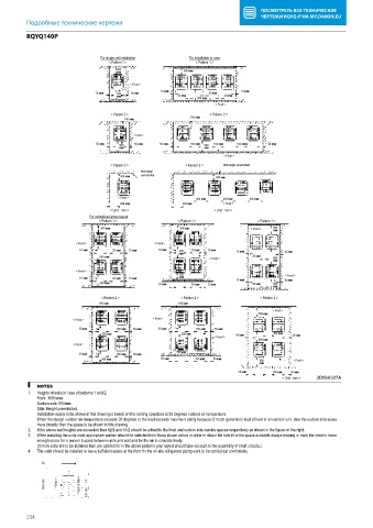
RQYQ140P
3 For single unit installation For installation in rows
< Pattern 1 > < Pattern 1 >
300 300 or more
or more
< Front >
10 or more 10 or more
10 or more 500 10 or more 20 or more
or more 20 or more 20 or more
500 or more
< Front >
< Pattern 2 > < Pattern 2 >
100 or more 100 or more
< Front >
50 or more 500 50 or more 50 or more 100 or more 500 100 or more 100 or more 50 or more
or more or more
< Front >
< Pattern 3 > < Pattern 3 > Wall heigh unrestricted
Wall heigh
300 or more unrestricted 300 or more
< Front > 400 or more 400 or more 400 or more
200 or more 200 or more < Front >
< Unit : mm > < Unit : mm >
For centralized group layout
< Pattern 1 > < Pattern 1 > < Pattern 1 >
300 or more 300 or more < Front > 500
or more
< Front > < Front >
10 or more 20 or more 10 or more 10 or more 500 20 or more 10 or more 10 or more 10 or more
600 or more or more < Front > 20 or more 900
or more
< Front >
300 < Front >
10 or more 20 or more 10 or more or more 10 or more 10 or more
500 or more 10 or more 20 or more 10 or more 20 or more 500
or more
< Pattern 2 > < Pattern 2 > < Pattern 2 >
100 or more 100 or more
< Front >
500 or more
< Front > < Front >
50 or more 100 or more 50 or more 50 or more 100 or more 50 or more
500 or more 500 or more 50 or more 100 or more 50 or more
< Front >
600 or more
< Front >
50 or more 100 or more 50 or more 100 or more
500 or more 50 or more 100 or more 50 or more 500 < Front >
or more
50 or more 100 or more 50 or more
< Unit : mm > 3D066327A
NOTES
1. Heights of walls in case of patterns 1 and 2:
Front: 1500 mm
Suction side: 500mm
Side: Height unrestricted.
Installation space to be shown in this drawing is based on the cooling operation at 35 degrees outdoor air temperature.
When the design outdoor air temperature exceeds 35 degrees or the load exceeds maximum ability because of much generation load of heat in all outdoor unit, take the suction side space
more broadly than the space to be shown in this drawing.
2. If the above wall heights are exceeded then h2/2 and h1/2 should be added to the front and suction side service spaces respectively as shown in the figure on the right.
3. When installing the units most appropriate pattern should be selected from those shown above in order to obtain the best fit in the space available always bearing in mind the need to leave
enough space for a person to pass between units and wall and for the air to circulate freely. .
(If more units are to be installed than are catered for in the above patterns your layout should take account to the possibility of short circuits.)
4. The units should be installed to leave sufficient space at the front for the on site refrigerant piping work to be carried out comfortably.
h2
1500 mm < Front > < Suction Side > h1 500 mm
234