
Page 237 - Каталог
P. 237
ПОСМОТРЕТЬ ВСЕ ТЕХНИЧЕСКИЕ
RWEYQ-T9 ЧЕРТЕЖИ RWEYQ-T9 НА MY.DAIKIN.EU
Подробные технические чертежи VRV, ВСТУПЛЕНИЕ
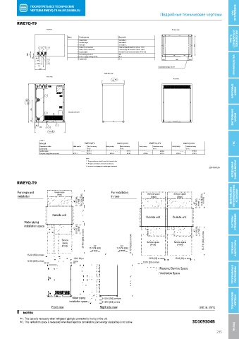
RWEYQ-T9
Top view Bottom view
Item Part name Remark СТАНДАРТЫ И
1 Liquid pipe See table 1. VRV IV, ТЕХНОЛОГИИ
2 Suction pipe See table 2.
3 Gas pipe See table 3. 516
3 2 1 4 Water IN connection External pipe thread ISO 228-G1 1/4 B
5 Water OUT connection External pipe thread ISO 228-G1 1/4 B
6 Drain outlet Flexible hose (inside diameter: Ø 10mm)
79 74 7 Grounding terminal M8
8 Power supply wiring intake Ø 25
25 88 9 Cable inlet Ø 25
134 9 80.5 600 80.5
179 8
224 Foundation bolt type: 4x Ø17 ПРЕИМУЩЕСТВА
269
Right-side view
Front view
Rear view
560
НАРУЖНЫЕ БЛОКИ
5
980
476
ВНУТРЕННИЕ БЛОКИ
Manufacturer label
4
92
88 7
288 6
767
Table 1
Model RWEYQ8T9 RWEYQ10T9 RWEYQ12T9 RWEYQ14T9 ГВС
Operation mode Heat pump Heat recovery Heat pump Heat recovery Heat pump Heat recovery Heat pump Heat recovery
Liquid pipe Ø 9.5 Ø 9.5 Ø 12.7 Ø 12.7
Suction pipe Ø 19.1 Ø 22.2 Ø 28.6 Ø 28.6
Gas pipe (high/low pressure) Ø 19.1 Ø 15.9 Ø 22.2 Ø 19.1 Ø 28.6 Ø 19.1 Ø 28.6 Ø 22.2
Notes
1. The grounding terminal is located in the switch box.
ВОЗДУШНАЯ ЗАВЕСА BIDDLE
2. The pipe connections are brazed connections.
3. In case of a heat pump, the suction pipe is not used.
2D108932A
RWEYQ-T9
RWEYQ-T9
For single unit Service space For installation Service space Service space
installation (Rear) in rows (Rear) (Rear) ВЕНТИЛЯЦИЯ И ВЕНТИЛЯЦИОННЫЕ УСТАНОВКИ
2 11-13/16 (300) or more 19-11/16 (500) or more 2 11-13/16 (300) or more 19-11/16 (500) or more
Outside unit
Outside unit Outside unit
Water piping СИСТЕМЫ УПРАВЛЕНИЯ
installation space
2 11-13/16 (300) or more 2 11-13/16 (300) or more
Service 35-7/16 (900) or more 35-7/16 (900) or more
space 11-13/16 (300) or more Service space Service space
2
(Front) 11-13/16 (300) 11-13/16 (300) (Front) (Front) ОПЦИИ И АКСЕССУАРЫ
2
or more or more
13-3/4 (350) or less
13/16 20) or 13/16 (20) or more 13/16 (20) or more
13-3/4 (350) or less more 13/16 (20) or more
ПРОГРАММЫ И ПЛАТФОРМЫ
: Required Service Space
: Ventilation Space
Water piping 3-15/16 (100) or more
installation space 9-13/16 (250) or less ТЕХНИЧЕСКИЕ ЧЕРТЕЖИ
Front view Right side view Unit: in. (mm)
NOTES
1. This space is necessary when refrigerant piping is connected to the top of the unit.
2. This ventialition space is necessary when heat rejection cancellation (Zero energy sissipation) is not active. 3D109304B
НАЗАД Технические чертежи
235