
Page 232 - Каталог
P. 232
ПОСМОТРЕТЬ ВСЕ ТЕХНИЧЕСКИЕ
ЧЕРТЕЖИ RQCEQ-P3 НА MY.DAIKIN.EU
Подробные технические чертежи
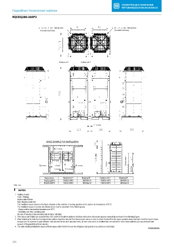
RQCEQ280-360P3
RQCEQ280-360P3
Oblong holes Oblong holes
(Foundation bolt holes) (Pitch of foundation bolt holes) (Pitch of foundation bolt holes) (Foundation bolt holes)
(Pitch of foundation bolt holes)
Outdoor unit 1 Outdoor unit 2
or more
SPACE EXAMPLE FOR INSTALLATION
or more
< Suction side >
< Front >
or more (Front) or more
or more or more
Model name Outdoor unit 1 Drawing N° Outdoor unit 2 Drawing N°
RQCEQ280P3 RQEQ140P3 3D066441A RQEQ140P3 3D066441A
RQCEQ360P3 RQEQ180P3 3D066441A RQEQ180P3 3D066441A
Unit: mm
NOTES
1. Heights of walls
Front: 1500mm
Suction side: 500mm
Side: Height unrestricted
The installation space shown in this figure is based on the condition of cooling operation at the outdoor air temperature of 35°C.
The installation space of suction side shown above must be expanded in the following case.
- Design outdoor temperature becomes over 35°C.
- Operating over Max. operating load
(In case of causing a heavy heating load at indoor unit side)
2. If the above wall heights are exceeded then h2/2 and h1/2 should be addes tot the front and suction side service spaces respectively as shown in the following figure.
3. When installing the units the most appropriate pattern should be selected from those shown above in order to obtain the best fit in the space available alway bearing in mind the need to leave
enough room for a person to pass between nuits and wall for the air to circulate freely. (If more units are to be installed than are catered for in the above patterns your layout should take
account of the possibility of short circuits.)
4. The units should be installed to leave sufficient space at the front for the on site refrigerant piping work to be carried out confortably.
3D066856A
230