
Page 228 - Каталог
P. 228
ПОСМОТРЕТЬ ВСЕ ТЕХНИЧЕСКИЕ
ЧЕРТЕЖИ RXYSQ-TY1 НА MY.DAIKIN.EU
Подробные технические чертежи
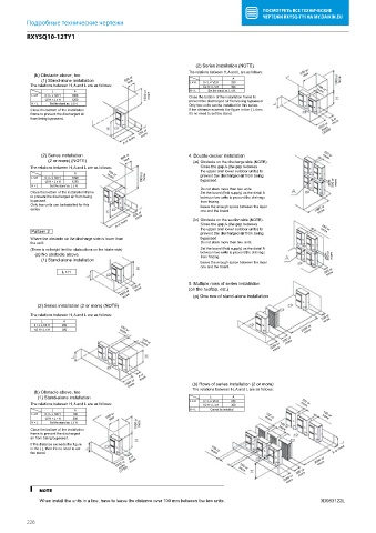
RXYSQ10-12TY1
RXYSQ10-12TY1
(2) Series installation (NOTE)
The relations between H, A and L are as follows: 500 or
(b) Obstacle above, too L A less
(1) Stand-alone installation 500 or L ≤ H 0 < L ≤ 1/2 H 250 1000 or more
less
The relations between H, A and L are as follows: 1/2 H < L ≤ H 300 100 or
L A H < L Set the stand as: L ≤ H. more
L ≤ H 0 < L ≤ 1/2 H 1000 1000 or more Close the bottom of the installation frame to
1/2 H < L ≤ H 1250 prevent the discharged air from being bypassed.
H < L Set the stand as: L ≤ H. Only two units can be installed for this series.
Close the bottom of the installation If the distance exceeds the figure in the ( ), then
frame to prevent the discharged air it’s no need to set the stand.
from being bypassed. A or
1500 or more
(2200)
250 or more
more
A or more
(2) Series installation 500 or 4. Double-decker installation more
100 or
(2 or more) (NOTE) less (a) Obstacle on the discharge side (NOTE).
The relations between H, A and L are as follows: Close the gap A (the gap between
L A 100 or the upper and lower outdoor units) to
L ≤ H 0 < L ≤ 1/2 H 1000 more 1000 or more prevent the discharged air from being
1/2 H < L ≤ H 1250 bypassed. 500 or
H < L Set the stand as: L ≤ H. more
Do not stack more than two units.
Close the bottom of the installation frame Set the board (field supply) as the detail A
to prevent the discharged air from being between two units to prevent the drainage
bypassed. from frozing.
Only two units can be installed for this Leave the enough space between the layer
series one and the board. 1000 or
more
300 or
more
A or more (b) Obstacle on the suction side (NOTE). 100 or
Close the gap A (the gap between
.
Pattern 2 the upper and lower outdoor units) to more
prevent the discharged air from being
Where the obstacle on the discharge side is lower than bypassed
the unit: Do not stack more than two units.
(There is no height limit for obstructions on the intake side) Set the board (field supply) as the detail A
between two units to prevent the drainage
(a) No obstacle above from frozing. 500 or more
(1) Stand-alone installation Leave the enough space between the layer
one and the board.
L ≤ H 300 or
more
1000 or 100 or 5. Multiple rows of series installation
more
(on the rooftop, etc.)
more
(a) One row of stand-alone installation
(2) Series installation (2 or more) (NOTE)
The relations between H, A and L are as follows: 100 or
L A more
0 < L ≤ 1/2 H 250
more
1/2 H < L ≤ H 300 more 2000 or
100 or
1000 or 200 or
more
100 or
more
more
A or more
1500 or (b) Rows of series installation (2 or more)
more
(b) Obstacle above, too The relations between H, A and L are as follows:
(1) Stand-alone installation L A
L ≤ H 0 < L ≤ 1/2 H 250 100 or
The relations between H, A and L are as follows: 1/2 H < L ≤ H 300 more
L A H < L Cannot be installed.
L ≤ H 0 < L ≤ 1/2 H 100 500 or 100 or 100 or
1/2 H < L ≤ H 200 less more more
H < L Set the stand as: L ≤ H. 1000 or more 100 or
Close the bottom of the installation more
frame to prevent the discharged
air from being bypassed.
If the distance exceeds the figure
in the ( ), then it’s no need to set 100 or A or more
the stand. more
A or
1000 or more more 3000 or
more
more
(1700)
100 or
1500 or 500 or
more
more
NOTE
When install the units in a line, have to leave the distance over 100 mm between the two units. 3D083122L
226