
Page 231 - Каталог
P. 231
ПОСМОТРЕТЬ ВСЕ ТЕХНИЧЕСКИЕ
ЧЕРТЕЖИ RXYLQ-T НА MY.DAIKIN.EU
Подробные технические чертежи VRV, ВСТУПЛЕНИЕ
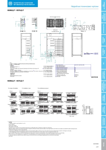
RXMLQ-T - RXYLQ-T
RXMLQ-T
RXYLQ-T 1 2 Pitch of foundation bolt holes E VRV IV, СТАНДАРТЫ И ТЕХНОЛОГИИ
1076
Pitch of foundation bolt holes 134 125 8
3 393
310 729
AB 192 112 107
71 70
100
106
160 10 ПРЕИМУЩЕСТВА
AA Oblong hole
Detail ·A· Detail ·B· Foundation bolt hole 4-15x22.5mm - View ·C·
11
RXMLQ-T
RXYLQ-T НАРУЖНЫЕ БЛОКИ
1685
4
For single unit installation For installation in rows 7 For centralized group layout
9 6
(Pattern 1) (Pattern 1) (Pattern 1) ВНУТРЕННИЕ
122 БЛОКИ
Model
300 or more 515 300 or more 300 or more 300 or more RYMQ14-16T, RXYQQ14-16T, REYQ14-20T 240 AA 205 AB
(FRONT)
500 or more
276 259 RYMQ18-20T, RXYQQ18-20T 240 210
10 or 10 or 179 131
10 or more (FRONT) more more 20 or more (FRONT) 20 or more 10 or more 10 or more (FRONT) 20 or more 10 or more (FRONT) 20 or more 10 or more
76 500 or more 500 or more 97 107 5 600 or more 10 or more 500 or more 10 or more 10 or more 20 or more 900 or more
76
137 DETAIL B DETAIL A 272
765 (Pattern 2) (Pattern 2) 328
100 or more 100 or more C 300 or more
373 10 or more (FRONT) 20 or more 10 or more 10 or more 10 or more 20 or more 500 or more 10 or more
500 or more
Notes
RXMLQ-T 1240 (Pattern 2) 20 or more 10 or more (FRONT) ГВС
1. Detail ·A· and detail ·B· indicate the dimensions after fixing the attached piping.
2. Items ·4 - 10:·Knockout hole.
RXYLQ-T 50 or
3. Gas pipe 50 or more (FRONT) more 50 or more 100 or more (FRONT) 100 or more 50 or more 11 Grounding terminal Inside of the switch box (·M8·)
500 or more
RXMLQ8T E 500 or more Ø ·19.1· brazing connection E 10 Pipe routing hole (bottom) 100 or (FRONT) 500 or more
RXYTQ10T, RXYLQ10T E RXMLQ-T Ø ·22.2· brazing connection 100 or 9 Pipe routing hole (front) more
RXYLQ-T
REYQ14-20T (Pattern 3) (Pattern 3) Ø ·25.4· brazing connection more 8 Power cord routing hole (bottom) Ø65
Wall height unrestricted
RYYQ14-20T, RYMQ14-20T, RXYQ14-20T, RXYQQ14-20T, RXYTQ12-16T, RXYLQ12-14T E Ø ·28.6· brazing connection 50 or morePower cord routing hole (front) 50 or (FRONT) Ø27 100 or more 50 or more
7
more 50 or more
100 or more
(FRONT)
Liquid pipe Wall height 6 Power cord routing hole (front) 500 or more Ø65 50 or more 50 or more
500 or more
unrestricted
300 or more
RXYTQ10T, RXMLQ8T, RXYLQ10T 300 or more E Ø ·9.5· brazing connection 5 Power cord routing hole (front) Ø80 100 or more 600 or more
E
RYYQ14-16T, RYMQ14-16T, RXYQ14-16T, RXYQQ14-16T, REYQ14-20T, RXYTQ12-16T, RXYLQ12-14T Ø ·12.7· brazing connection 4 Power cord routing hole (side) 100 or Ø65
RYYQ18-20T, RYMQ18-20T, RXYQ18-20T, RXYQQ18-20T
Ø ·15.9· brazing connection
For single unit installation For installation in rows For centralized group layout 50 or more Equalising pipe connection port 50 or more more 300 or more See note ·3·.
(FRONT)
Equalising pipe
100 or more
3
400 or more
(FRONT)
RYMQ14-16T (FRONT) 400 or more Ø ·22.2· brazing connection High pressure/low pressure gas pipe 50 or more 100 or more 50 or more 50 or more 100 or more (FRONT) 50 or more
500 or more
200 or more
For installation in rows
RYMQ18-20T For single unit installation 200 or more Ø ·28.6· brazing connection 2 Gas pipe connection port See note ·3·. 500 or more ВОЗДУШНАЯ ЗАВЕСА BIDDLE
For centralized group layout
High pres (Pattern 1) (Pattern 1) 1 Liquid pipe connection port See note ·3·.
(Pattern 1)sure/low pressure gas pipe
REYQ14-20T Ø ·22.2· brazing connection No. Part name Remark <Unit = mm>
2D079533E
(Pattern 1)
300 or more 300 or more (Pattern 1) 300 or more 300 or more (Pattern 1) (FRONT) 500 or more
RXMLQ-T 300 or more 300 or more 300 or more 300 or more
RXYLQ-T 10 or 10 or (FRONT) 500 or more
RXMLQ-T - RXYLQ-T (FRONT) 20 or more 10 or more 10 or more (FRONT) 20 or more 10 or more (FRONT) 20 or more
10 or more
more
more
20 or more
(FRONT)
10 or
500 or more 500 or more 10 or more (FRONT) 10 or 600 or more 20 or more (FRONT) 10 or more 500 or more 10 or more 10 or more 20 or more 10 or more
more
more
10 or more 10 or more
20 or more
20 or more
(FRONT)
500 or more 500 or more (FRONT) 10 or more 10 or more 900 or more 20 or more 10 or more 10 or more 20 or more 10 or more
500 or more
600 or more
(Pattern 2) (Pattern 2) 900 or more
100 or more 100 or more (Pattern 2) 10 or more (Pattern 2) 20 or more 10 or more 300 or more
100 or more (FRONT) 100 or more 20 or more 500 or more 10 or more
300 or more
500 or more 10 or more 10 or more 500 or more 20 or more (FRONT) 10 or more 20 or more 500 or more 10 or more ВЕНТИЛЯЦИЯ И ВЕНТИЛЯЦИОННЫЕ УСТАНОВКИ
10 or more 10 or more
20 or more (FRONT)
10 or more
<Front>
(Pattern 2)
For single unit installation For installation in rows For centralized group layout (Pattern 2) 10 or more 20 or more 10 or more (FRONT)
50 or
50 or more (FRONT) more 50 or more 100 or more (FRONT) 100 or more 50 or more 50 or <Suction side>
500 or more 500 or more 50 or more (FRONT) more 50 or more 100 or more (FRONT) 100 or 100 or more 50 or more (FRONT) 500 or more
500 or more
500 or more
(Pattern 1)
(Pattern 1) (Pattern 1) 100 or more 100 or 100 or (FRONT) 500 or more
more
more
(Pattern 3) (Pattern 3) Wall height unrestricted (Pattern 3) (Pattern 3) more 50 or
300 or more Wall height 300 or more 50 or more Wall height 300 or more 100 or more 50 or Wall height unrestricted (FRONT) 100 or more (FRONT) 50 or more more 50 or more 500 or more 100 or more 50 or more
more 50 or more
(FRONT)
100 or more
300 or more 50 or more
(FRONT)
(FRONT)
300 or more unrestricted 300 or more 300 or more unrestricted 500 or more 300 or more 500 or more 500 or more 50 or more 100 or more 500 or more 50 or more 50 or more 100 or more 600 or more 50 or more
600 or more
10 or 10 or 100 or 100 or
10 or more (FRONT) more more 20 or more (FRONT) 20 or more 10 or more 10 or more (FRONT) 20 or more 10 or more more (FRONT) 20 or more (FRONT) 100 or more 50 or more more 300 or more
300 or more 50 or more
50 or more
10 or more 10 or more
(FRONT)
400 or more
500 or more 500 or more (FRONT) 600 or more 100 or more 50 or more 400 or more 500 or more 20 or more 50 or more 10 or more
500 or more
10 or more
100 or more
(FRONT)
(FRONT) 400 or more (FRONT) 400 or more 200 or more 500 or more 200 or more 50 or more 100 or more 50 or more 50 or more 100 or more 900 or moreNT) 50 or more 50 or more 50 or more 100 or more (FRONT) 50 or more
(FRO
200 or more 200 or more NOTES 500 or more 500 or more СИСТЕМЫ УПРАВЛЕНИЯ
(Pattern 2) (Pattern 2) 1. Heights of walls in case of patterns 1 and 2:
100 or more 100 or more 10 or more (FRONT) 20 or more 10 or more 300 or more <Unit = mm> <Unit = mm>
Front: 1500mm
Suction side: 500mm 500 or more 10 or more 20 or more 10 or more 10 or more 20 or more 500 or more 10 or more
Side: Height unrestricted (FRONT)
(Pattern 2)
50 or Installation space as shown on this drawing is based on the cooling operation at 35 degrees outdoor air temperature.
50 or more (FRONT) more 50 or more 100 or more When the design outdoor air temperature exceeds 35 degrees or the load exceeds maximum ability of much generation load of heat in all outdoor unit, take the suction side space more
100 or more
(FRONT)
50 or more
500 or more 500 or more
broadly than the space as shown on this drawing. 100 or (FRONT) 500 or more
100 or
more
more
(Pattern 3) (Pattern 3) 2. If the above wall heights are exceeded then h2/2 and h1/2 should be added to the front and suction side service spaces respectively as shown in the figure on the right.
50 or
Wall height unrestricted
100 or more
(FRONT)
50 or more
50 or more
more 50 or more
Wall height 3. When installing the units most appropriate pattern should be selected from those shown above in order to obtain the best fit in the
(FRONT)
100 or more
50 or more
500 or more
50 or more
500 or more
100 or more
300 or more unrestricted space available. Always keep in mind the need to leave enough space for a person to pass between units and wall and also for the air to circulate freely. <Front> ОПЦИИ И АКСЕССУАРЫ
300 or more
(If more units are to be installed than are catered for in the above patterns your layout should take account of the possibility of short circuits).
600 or more
100 or
4. The units should be installed to leave sufficient space at the front for the on site refrigerant piping work to be carried out comfortably. <Suction side>
more
3D079542 50 or more (FRONT) 100 or more 50 or more 300 or more <Front>
(FRONT) 400 or more (FRONT) 400 or more 500 or more 50 or more 100 or more 50 or more 50 or more (FRONT) <Suction side> 50 or more
200 or more 200 or more 100 or more 500 or more
<Unit = mm>
NOTES
1. Heights of walls in case of patterns 1 and 2:
Front: 1500mm ПРОГРАММЫ И ПЛАТФОРМЫ
NOTES Suction side: 500mm
1. Heights of walls in case of patterns 1 and 2: Side: Height unrestricted
Installation space as shown on this drawing is based on the cooling operation at 35 degrees outdoor air temperature.
Front: 1500mm When the design outdoor air temperature exceeds 35 degrees or the load exceeds maximum ability of much generation load of heat in all outdoor unit, take the suction side space more
Suction side: 500mm broadly than the space as shown on this drawing.
<Suction side>
Side: Height unrestricted 2. If the above wall heights are exceeded then h2/2 and h1/2 should be added to the front and suction side service spaces respectively as shown in the figure on the right.
Installation space as shown on this drawing is based on the cooling operation at 35 degrees outdoor air temperature. <Front>
3. When installing the units most appropriate pattern should be selected from those shown above in order to obtain the best fit in the
When the design outdoor air temperature exceeds 35 degrees or the load exceeds maximum ability of much generation load of heat in all outdoor unit, take the suction side space more
space available. Always keep in mind the need to leave enough space for a person to pass between units and wall and also for the air to circulate freely.
broadly than the space as shown on this drawing. (If more units are to be installed than are catered for in the above patterns your layout should take account of the possibility of short circuits).
2. If the above wall heights are exceeded then h2/2 and h1/2 should be added to the front and suction side service spaces respectively as shown in the figure on the right.
4. The units should be installed to leave sufficient space at the front for the on site refrigerant piping work to be carried out comfortably.
3D079542
3. When installing the units most appropriate pattern should be selected from those shown above in order to obtain the best fit in the
space available. Always keep in mind the need to leave enough space for a person to pass between units and wall and also for the air to circulate freely. ТЕХНИЧЕСКИЕ ЧЕРТЕЖИ
(If more units are to be installed than are catered for in the above patterns your layout should take account of the possibility of short circuits).
4. The units should be installed to leave sufficient space at the front for the on site refrigerant piping work to be carried out comfortably.
3D079542
NOTES
1. Heights of walls in case of patterns 1 and 2:
Front: 1500mm
Suction side: 500mm
Side: Height unrestricted
Installation space as shown on this drawing is based on the cooling operation at 35 degrees outdoor air temperature.
When the design outdoor air temperature exceeds 35 degrees or the load exceeds maximum ability of much generation load of heat in all outdoor unit, take the suction side space more 3D079542 НАЗАД Технические чертежи
broadly than the space as shown on this drawing.
2. If the above wall heights are exceeded then h2/2 and h1/2 should be added to the front and suction side service spaces respectively as shown in the figure on the right. 229
3. When installing the units most appropriate pattern should be selected from those shown above in order to obtain the best fit in the
space available. Always keep in mind the need to leave enough space for a person to pass between units and wall and also for the air to circulate freely.
(If more units are to be installed than are catered for in the above patterns your layout should take account of the possibility of short circuits).
4. The units should be installed to leave sufficient space at the front for the on site refrigerant piping work to be carried out comfortably.
3D079542
3D079542
3D079542
3D079542