Page 246 - Каталог
P. 246

ПОСМОТРЕТЬ ВСЕ ТЕХНИЧЕСКИЕ
                                                                                    ЧЕРТЕЖИ FXDQ-A3 НА MY.DAIKIN.EU
          Подробные технические чертежи
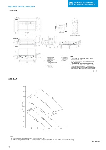
          FXDQ63A3

          FXDQ63A

                   300 or more            300 or more
                  (Service space of       (Service space)
                  installation box
                  for adapter PCB)
                                             (Suspension bolt pitch)  20 or more  20 or more  400 or more  240 or more
                                                                   (In case of
                                                                   bottom-suction)


                                                                          Ceiling
                           26x ø 4,7 holes
                                                                   Service space
                            (Suspension bolt pitch)                                  View A
                                                                                Inspection door (ceiling opening)
                                         300 or less
                                                                 Adjustable (0-600)  24xM5 holes
               Suspension bolt

                 18xM4 holes

                                                                            In case of back suction

                                           24xM5 holes
                                                                                Notes:
                                                   1                Liquid pipe connection                                             ø 9.5 Flare connection
                                                   2                Gas pipe connection                                                  ø 15,9 Flare connection  1. In case of back-suction, mount chamber cover to
                                                   3                Drain piping connection                                          VP20 (O.D. ø  26, I.D. ø  20)      bottom side of the unit.
                                                   4               Drain hose (accesory)                                                 ID  ø  25 (Outlet)
                                                   5                control box      In case of bottom-suction, mount chamber cover to
                                                   6                Transmission wiring connection      back side of the unit.
                                                   7                Power supply connection  2. Locations of unit’s name plate: control box cover.
                          In case of bottom-suction  8               Suspension bracket
                                                   9               Inspection cover                                    3. Mount the air  lter at the suction side. (Use an air  lter
                                                   10               Socket for drain      whose dust collecting e ciency is at least 50% in a
                                                   11               Air  lter (accessory)      gravimetric technique). It can not be equipped with air
                                                                                     lter (accessory) when connecting duct to suction side.
                                                                                                       3D081441
          FXDQ15A3
          FXDQ15A3


                           40


                           35
                                Upper limit of ESP
                           30                              High ESP

                          External static pressure [Pa]  25  High ESP  High ESP


                           20
                                Standard ESP
                           15  Upper limit of ESP
                                                            High ESP
                                                           Lower limit of ESP
                           10                  Standard ESP  Standard ESP


                           5           Standard ESP

                           0
                                    6     6.5    7      7.5    8     8.5    9
                                                Air  ow rate [m³/min]


             Notes
             The remote controller can be used to switch between 'high' and 'low'.
             The air  ow is factory-set to 'standard'. It is possible to switch between 'standard ESP' and 'high  ESP' by remote controller setting.
                                                                                                        3D081424C

          244
   241   242   243   244   245   246   247   248   249   250   251