Page 269 - Каталог
P. 269

ПОСМОТРЕТЬ ВСЕ ТЕХНИЧЕСКИЕ
                ЧЕРТЕЖИ FXNQ-A НА MY.DAIKIN.EU
                                                                                 Подробные технические чертежи       VRV,   ВСТУПЛЕНИЕ
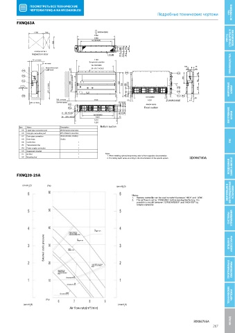
          FXNQ63A
     FXNQ63A

                  1190  300                        ARROW VIEW B
                                                 1080
                                                 1060                                                                VRV IV,   СТАНДАРТЫ И   ТЕХНОЛОГИИ
                                                6x150= 900
                            620
                                                              80  156  170  200
                  ARROW VIEW A
                 Inspection door                        18-M4  57.5  19.5  12.5
                 20  or more                     1140

                      20  or more             Suspension position                                                     ПРЕИМУЩЕСТВА

                                               10x100= 1000                                   100   48
                        Suspension bolt        26- Ø4.7 HOLE                                   24   90
            KB          4-M8~M10     60
                                                                 KH                        KH
            KA                                                                                330    130
            KC                       500  Suspension position  620                                   63
                                                100  or more                                         310
          ARROW VIEW                                           723  100  179.4             KD
            A                                                                              KF                        НАРУЖНЫЕ   БЛОКИ
            KK                                                   48  8.4   9x100= 900      KJ  KE
                              300  or more       1190             50        1001      24-Ø4.3 HOLE  171  46

                240  or more  Service space                   10  42  50
                                    KJ                                     ARROW VIEW B
                                    KG                                    Front suction
                                4- Ø5 HOLE
                                                9x100= 900    180  116  100                                          ВНУТРЕННИЕ   БЛОКИ
                                24- Ø4.3 HOLE    1001        75
                                                 1210
                                                 1230
           Item  Name           Description         Bottom suction
            KA  Liquid pipe connection port  Ø9.52 flared connection
            KB  Gas pipe connection port  Ø15.9 flared connection
            KC  Drain pipe connection  VP20 (OD Ø26, ID Ø20)
            KD  Drain hose      ID Ø25
            KE  Control box              /                                                                            ГВС
            KF  Transmission line        /
            KG  Power supply connection  /
            KH  Suspension bracket       /
            KJ  Air filter               /            Notes
                                                       1. When installing optional accessories, refer to their respective documentation.
            KK  Mounting foot            /             2. The ceiling depth varies according to the documentation of the specific system.  3D096740A
                                                                                                                     ВОЗДУШНАЯ   ЗАВЕСА BIDDLE
          FXNQ20-25A
 FXDQ20-25A
            (mmH 2 O)    (Pa)                               (mmH 2 O)

                                                                    Notes:                                          ВЕНТИЛЯЦИЯ И   ВЕНТИЛЯЦИОННЫЕ   УСТАНОВКИ
                                                                    1.   Remote controller can be used to switch between `HIGH` and `LOW`.
                                                                    2.   The air  ows is set to `STANDARD` before leaving the factory. It is
                                                                       possible to switch between `STANDARD ESP` and `HIGH ESP` by
                                                                       remote controller.
                                                                                                                     СИСТЕМЫ   УПРАВЛЕНИЯ


                                                 H (High ESP)
                                    Upper limit of
                                    external static H
                                    pressure (high ESP)
                       External static pressure  Low  (High ESP)                                                     ОПЦИИ И   АКСЕССУАРЫ

                                    (High ESP)


                                               Lower limit of external
                                               static pressure (high
                                               ESP)
                              Upper limit of                                                                         ПРОГРАММЫ И   ПЛАТФОРМЫ
                              external static
                              pressure (standard
                              ESP)
                                      H
                                   (Standard ESP)
                                       M
                                   (Standard ESP)
                                                                                                                     ТЕХНИЧЕСКИЕ   ЧЕРТЕЖИ
                                   Low
                               (Standard ESP)
                        (Pa)
             (mmH 2 O)                                       (mmH 2 O)
                                    Air flow rate(m³/min)
                                                                                                   3D086736A          НАЗАД Технические чертежи
                                                                                                             267
   264   265   266   267   268   269   270   271   272   273   274