
Page 274 - Каталог
P. 274
ПОСМОТРЕТЬ ВСЕ ТЕХНИЧЕСКИЕ
ЧЕРТЕЖИ FTXJ-MW НА MY.DAIKIN.EU
Подробные технические чертежи
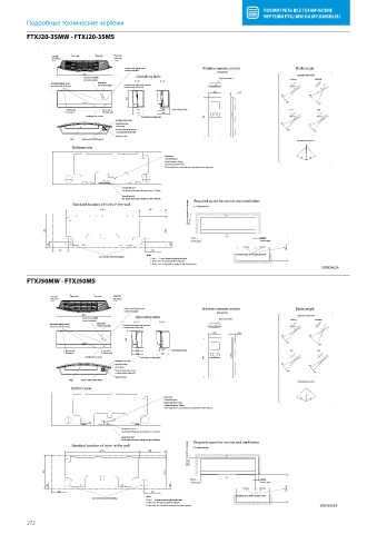
FTXJ20-35MW - FTXJ20-35MS
FTXJ20-35MW
FTXJ20-35MS
Left side Rear side Rear side Right side
See note 2. See note 2.
Service cover xing screw Wireless remote control Blade angle
On the front grille
(ARC466A9)
998 Up/down (automatic)
Earth terminal (M4) Operating state Signal transmitter
On the front grille ) 1 O F F ) 2 O n Cooling Heating
Front grille xing screws Nameplate Terminal block with earth terminal
On the front grille
Located inside of the unit Located inside of the unit
58.5 21.5
20° 30°
303
50°
70°
Bottom side See note 3. 212 18 Air discharge range Fan Dry
See note 3. Bottom side 214 238
Intelligent Eye sensor Including mounting plate 189
Intelligent Eye lamp
Operation lamp 25° 25°
Timer lamp
Room temperature sensor 50°
Located inside of the unit 50°
Signal receiver
Flap Indoor unit On/OFF switch
Left/right (automatic)
Bottom view
Drain hose
35° 35°
Connecting part
Inside diameter: 16mm
Outside diameter: 18mm
The length of the connection hose outside the unit is 465mm.
Gas pipe ø9.5CuT
The length of the pipe outside the unit is 350mm.
Liquid pipe ø6.4
The length of the pipe outside the unit is 400mm. Required space for service and ventilation
Minimum space for air passage
Standard location of holes in the wall Indoor air ow
674.5 200
20
303 270.5 30 min
50min 50min
Service space Service space
49 49
350min 250 min 500 min
142 151
Notes Required space for the signal receiver
ø 65 Hole for embedded piping
1. The ·( )· mark shows the piping direction.
2. In this case, the optional grille is required.
3. In this case, cut the grille according to the paper pattern.
2D092462A
FTXJ50MW - FTXJ50MS
FTXJ50MW
FTXJ50MS
Left side Rear side Rear side Right side
See note 2. See note 2.
Service cover xing screw Wireless remote control Blade angle
On the front grille
(ARC466A9)
998 Operating state Up/down (automatic)
Earth terminal (M4) Signal transmitter
On the front grille ) 1 O F F ) 2 O n Cooling Heating
Front grille xing screws Nameplate Terminal block with earth terminal
Located inside of the unit On the front grille Located inside of the unit
58.5 21.5
20° 30°
303
50°
70°
Bottom side See note 3. 212 18 Air discharge range Fan Dry
See note 3. Bottom side 214 238
Intelligent Eye sensor Including mounting plate 189
Intelligent Eye lamp
Operation lamp 25° 25°
Timer lamp
Room temperature sensor 50° 50°
Located inside of the unit
Signal receiver
Flap Indoor unit On/OFF switch
Left/right (automatic)
Bottom view
Drain hose 35˚ 35˚
Connecting part
Inside diameter: 16mm
Outside diameter: 18mm
The length of the connection hose outside the unit is 465mm.
Gas pipe ø12.7CuT
The length of the pipe outside the unit is 350mm.
Liquid pipe ø6.4
The length of the pipe outside the unit is 400mm. Required space for service and ventilation
Minimum space for air passage
Standard location of holes in the wall Indoor air ow
674.5 200
20
303 270.5 30 min
50min 50min
Service space Service space
49 49
350min 250 min 500 min
142 151
Notes Required space for the signal receiver
ø 65 Hole for embedded piping
1. The ·( )· mark shows the piping direction.
2. In this case, the optional grille is required.
3. In this case, cut the grille according to the paper pattern. 2D092503A
272