
Page 283 - Каталог
P. 283
ПОСМОТРЕТЬ ВСЕ ТЕХНИЧЕСКИЕ
ЧЕРТЕЖИ HXHD-A8 НА MY.DAIKIN.EU
Подробные технические чертежи VRV, ВСТУПЛЕНИЕ
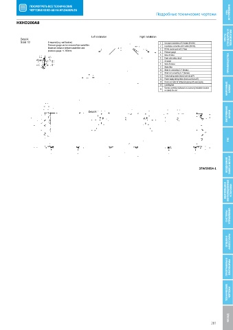
HXHD200A8
HXHD200A8 Left installation Right installation
Detail A VRV IV, СТАНДАРТЫ И ТЕХНОЛОГИИ
Scale 1/3 If required (e.g. wall fixation) 1 Gas pipe connection ø15.9 solder (R410A)
Pressure gauge can be removed from waterfilter. 2 Liquid pipe connection ø9.5 solder (R410A)
Maximum distance between waterfilter and 3 R134a service ports ø12.7 flare
pressure gauge: +/- 600mm.
4 Pressure gauge
5 Blow off valve
6 Drain valve water circuit
7 Air purge
8 Shut-off valves ПРЕИМУЩЕСТВА
9 Water filter
10 Water in connecting G 1” (female)
11 Water out connecting G 1” (female)
HXHD200A8 Left installation 12 Control wiring intake (knock-out hole ø37)
Right installation
Detail A 13 Power supply wiring intake (knock-out hole ø37)
Scale 1/3 If required (e.g. wall fixation) 1 Gas pipe connection ø15.9 solder (R410A)
Pressure gauge can be removed from waterfilter. 14 Knock-out holes for refrigerant piping and water piping
Maximum distance between waterfilter and 15 Levelling feet 2 Liquid pipe connection ø9.5 solder (R410A)
3
R134a service ports ø12.7 flare
pressure gauge: +/- 600mm. Remote controller (delivered as accessory) installation location
4
Pressure gauge
16 is outside the unit 5 Blow off valve НАРУЖНЫЕ БЛОКИ
6 Drain valve water circuit
7 Air purge
8 Shut-off valves
9 Water filter
10 Water in connecting G 1” (female)
11 Water out connecting G 1” (female)
12 Control wiring intake (knock-out hole ø37)
13 Power supply wiring intake (knock-out hole ø37)
14 Knock-out holes for refrigerant piping and water piping
Detail A 15 Levelling feet
16 Remote controller (delivered as accessory) installation location ВНУТРЕННИЕ БЛОКИ
is outside the unit
Detail A
ГВС
ВОЗДУШНАЯ ЗАВЕСА BIDDLE
3TW59854-1
3TW59854-1
ВЕНТИЛЯЦИЯ И ВЕНТИЛЯЦИОННЫЕ УСТАНОВКИ
СИСТЕМЫ УПРАВЛЕНИЯ
ОПЦИИ И АКСЕССУАРЫ
ПРОГРАММЫ И ПЛАТФОРМЫ
ТЕХНИЧЕСКИЕ ЧЕРТЕЖИ
НАЗАД Технические чертежи
281