Page 282 - Каталог
P. 282

ПОСМОТРЕТЬ ВСЕ ТЕХНИЧЕСКИЕ
                                                                                    ЧЕРТЕЖИ HXHD-A8 НА MY.DAIKIN.EU
          Подробные технические чертежи
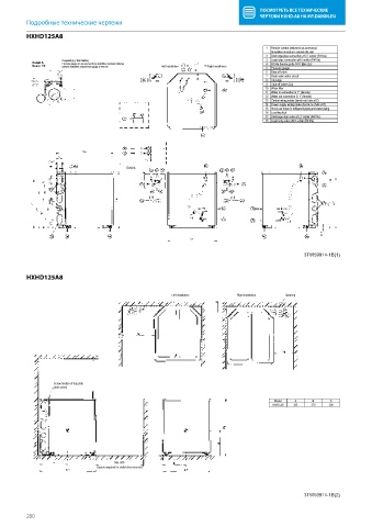
          HXHD125A8
           HXHD-A
                                                                                      1  Remote control (delivered as accessory)
                                                                                        Installation location is outside the unit
                                                                                      2  Discharge pipe connection ø12.7 solder (R410a)
                     If required (e.g. Wall  fixation)                                3  Liquid pipe connection ø9.5 solder (R410a)
           Detail A  Pressure gauge can be removed from waterfilter, maximum distance  4  R134a Service ports 5/16”   are (2x)
           Scale 1/3  between waterfilter and pressure gauge ± 600 mm  Left Installation  Right installation  5  Pressure gauge
                                                                                      6  Blow off valve
                                                                                      7  Drain valve water circuit
                                                                                      8  Air purge
                                                                                      9  Shut-off valves (2x)
                                                                                      10 Wster filter
                                                                                      11  Water in connection G 1° (female)
                                                                                      12 Water out connection G 1° (female)
                                                                                      13 Control wiring intake (knock-out hole ø37)
                                                                                      14 Power supply wiring intake (knock-out hole ø37)
                                                                                      15 Knock-out holes for refrigerant piping and water piping
                                                                                      16 Levelling feet
                                                                                      17 Discharge stop valve ø12.7 solder (R410a)
                                                                                      18 Liquid stop valve ø9.5 solder (R410a)


                                          Detail A


                                                                                                  3TW59914-1B(1)


          HXHD125A8
           HXHD-A
                                                        Left Installation    Right installation  Upwiring


                  Screw fixation of top plate
                  (both sides)

                                                                                         Model  A    B     C
                                                                                        HXHD-A8  355  270  300


                                      Min. 600
                                (Space required for switch box removal)


                                                                                                  3TW59914-1B(2)


          280
   277   278   279   280   281   282   283   284   285   286   287