Page 252 - Каталог
P. 252

ПОСМОТРЕТЬ ВСЕ ТЕХНИЧЕСКИЕ
                                                                                    ЧЕРТЕЖИ FXSQ-A НА MY.DAIKIN.EU
          Подробные технические чертежи
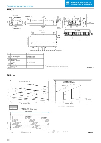
        FXSQ140A
          FXSQ140A


                  Ø100
                 (                              )   1550              69
                 Knockout hole.
            170  Fresh air intake position  Suspension bolt  1342     40      25        800
                                                      50                 109  130  KJ  301  KC  KE  KH  300  or more  Service space
                                  100  65                             38  62  2x65=
          140
                               245  178                                                             110  210  ARROW VIEW A
                                                                             KK
                 126 P.C.D.                      8x156= 1248         32      KF   179  50  KD       50
                                                   1365             500  or more
                 4 x M4 (CLASS 2)                                   Service space
                                                                                           1504
                                               1588  Suspension position                  9x150= 1350
                                      60         18x65= 1170     60
                                                                                                             95  210
                                                                      KA
                                                                      KB              KG  ARROW VIEW A  KG
                                  630 Suspension position


                                    42  151 123 122 123 116 115 151 123 122 123 116  10x Ø4.7 HOLE

          Item  Name            Description
           KA  Liquid pipe connection port  Ø9.52 flared connection
           KB  Gas pipe connection port  Ø15.90 flared connection
           KC  Drain pipe connection  VP20 (OD Ø26, ID Ø20)
           KD  Wiring connection          /
           KE  Power supply connection    /
           KF  Drain outlet     VP20 (OD Ø26, ID Ø20)
           KG  Air filter                 /
           KH  Air suction side           /
           KJ  Air discharge side         /           Notes
                                                       1. When installing optional accessories, refer to their respective documentation.
           KK  Nameplate                  /            2. The ceiling depth varies according to the documentation of the specific system.  3D094928A


          FXSQ15A
          FXSQ15A

            200                                                 200
                        Fan characteristics (1)                            Fan   characteristics  (3)


                                                                            Air   flow autoadjustment
                                       H-Tap   *1

            150  Upper   limit of ESP  M-Tap  *1      *1        150       Upper   limit of ESP  1.
           External static pressure [Pa]        100  L-Tap L T  limit of  *2 (*1) (*1) L-Tap  *2  M-Tap  *2  Lower   limit of ESP *2   *2   [Pa]  static pressure     100  L-Tap  M-Tap  H-Tap
                   *1

                                                  Lower
                                                    limit of ESP

                                                     H-Tap
                     *1
                   Upper
                     L T  ESP


                                                                 50
             50
                   *3
               Upper

                  limit of ESP

                              L-Tap *3  M-Tap  *3  H-Tap  *3   External                       2.   Lower   limit of ESP


             0                                   Lower   limit of ESP *3  0
              5,5       6,5      7,5       8,5       9,5          5,5      6,5       7,5      8,5      9,5


                          Air   flow rate  [m³/min]                           Airflow rate [m /min]
                                                                                    3


                                                                     1. Upp  er limit of ESP by air flow auto adjustment


            Mark   ESP [Pa]                                          2. Low  er limit of ESP by air flow auto adjustment
            *1  MAX  150
            *2  -   100

            *3  STD  50   Fan characteristics (2)
                          Field setting with remote control


                               Air   flow rate range  (H)
             200
             190
             180
             170
             160
             150
             140
             130
             120
             110
             100
            [Pa]  90
             80
            static pressure     50
             70
             60
             40
             30
             20
           External   10 0  5 , 7  Airflow rate [m 3  5 , 8  5 , 9  1. The   fan characteristics shown are in "fan only" mode.  3D096999
                                                                Notes
                                 /min]


                                                               2. ESP:

                                                                  External Static Pressure
          250
   247   248   249   250   251   252   253   254   255   256   257