Page 259 - Каталог
P. 259

ПОСМОТРЕТЬ ВСЕ ТЕХНИЧЕСКИЕ         ПОСМОТРЕТЬ ВСЕ ТЕХНИЧЕСКИЕ
                ЧЕРТЕЖИ FXMQ-P7 НА MY.DAIKIN.EU    ЧЕРТЕЖИ FXMQ-MB НА MY.DAIKIN.EU
                                                                                 Подробные технические чертежи       VRV,   ВСТУПЛЕНИЕ
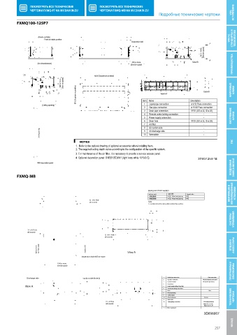
          FXMQ100-125P7
           FXMQ100-125P7

                    (Knock out hole)                                                                                  СТАНДАРТЫ И
                       Fresh air intake position                                                                     VRV IV,   ТЕХНОЛОГИИ
                                                                   Suspension bolt
                                                                                                      350 or more  (Service space)


                                                                   500 or more                    Detail B
                    (On circumference)
                                                                   (Service space)                                    ПРЕИМУЩЕСТВА
                                                1438 (Suspension position)
                                390 or more  (Service space)
                                       631 (Suspension position)                  View A-A             Detail B      НАРУЖНЫЕ   БЛОКИ


                                                                         1
                                                                                                 ø 9.52 Flare connection
                                                                            Liquid pipe connection
                      (Ceiling opening)                                  Item Name               Description
                                                                         2  Gas pipe connection   ø 15.90 Flare connection
                                                                         3  Drain pipe connection  VP25 (OD ø 32, ID ø 25)
                                                                         4  Remote control wiring connection  -      ВНУТРЕННИЕ
                                                                         5  Power supply connection    -               БЛОКИ
                                                                         6  Drain hole           VP25 (OD ø 32, ID ø 25)
                                                                                                       -
                                                                         8  Air suction side           -
                     (Ceiling opening)                                   10 9  Air discharge side      - -
                                                                            Nameplate
                                         NOTES                                                                        ГВС
                                       1.  Refer to the outlook drawing of optional accessories when installing them.

                                       2. The required ceiling depth varies according to the configuration of the specific system.
                                       3. For maintenance of the air filter, it is necessary to provide a service access panel.


                                       4. Optional decoration panel: BYBS125DJW1 (light ivory white 10Y9/0.5)  3TW31254-1B
                                                                                                                     ВОЗДУШНАЯ   ЗАВЕСА BIDDLE
                    With decoration panel
          FXMQ-MB


                                                                           piping size (Field supply)
                                                                            indoor unit  gas side  liquid side      ВЕНТИЛЯЦИЯ И   ВЕНТИЛЯЦИОННЫЕ   УСТАНОВКИ
                                                                                       Attached piping
                                                                                       Attached piping
                                              32 - ø 4.7 Hole
                                              (all around)                  Note
                                                                            1. Location of unit`s name plate: Control box surface
                                                                                                                     СИСТЕМЫ   УПРАВЛЕНИЯ


               32 - ø 4.7 Hole
               (all around)
                                                      32 - ø 4.7 Hole
                                                      (all around)
                   650 or more  (service space)  approx. 600     View A                                              ОПЦИИ И   АКСЕССУАРЫ

                                          Inspection hole 600 or more
                                                                                                                     ПРОГРАММЫ И   ПЛАТФОРМЫ
                              1100 or more
                              (Service space)

              Discharge side               suction side (Note 2)                   1              Liquid pipe connection                                                   Flare connection
                                                                                   2              Gas pipe connection                                                                                           Attendant piping connection
                                                                                   3              Ground terminal                                                                                                          M5 (inside switch box)
                                                                                   4              Control box
              View A                                                               5              Power supply wiring connection
                                                                                   6              Transmision wiring connection
                                                                                   7              Hook                                                                      M10
                                                                                   8              Discharge  ange
                                                                                   9              Suction  ange
                                                                                   10            Attached piping                                                                                                               Brazing  ТЕХНИЧЕСКИЕ   ЧЕРТЕЖИ
                                                                                   11            Name plate
                                                      16 - ø 8 Hole                12             Drain piping connection                                                                                           PS1B internal thread
                                                      (all around)                                                                            Major dia. ø33.349
                                                                                                                                                Major dia. ø33.391
                                                                                   13           Water supply port
                                                                                                       3D096007
                                                                                                                      НАЗАД Технические чертежи
                                                                                                             257
   254   255   256   257   258   259   260   261   262   263   264